The Ambassador TR dumbwaiter quickly and quietly carries up to 500 pounds at speeds up to 300 feet per minute.
The counterweighted TR is unparalleled for moving everything from office files to hospital supplies in high-rise applications, eliminating delays, inconvenience and congestion in busy elevators. Imagine the time and effort it can save! If you’re looking for cost efficiencies and labor savings, the reliable Ambassador TR is the answer. Which is why you’ll find it being used in successful hospitals, office buildings, colleges, banks, and museums, all across the country. Installing an Ambassador reflects the kind of smart thinking it takes to help organizations like these afford to occupy tall buildings in the first place.
- SPEED: Up to 300 F.P.M.
- CAPACITY: Up to 500 Ibs.
- TRAVEL: Unlimited.
- Flexible design allows both light and heavy carrying capacity.
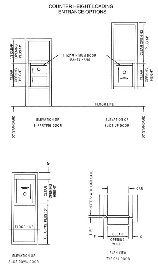
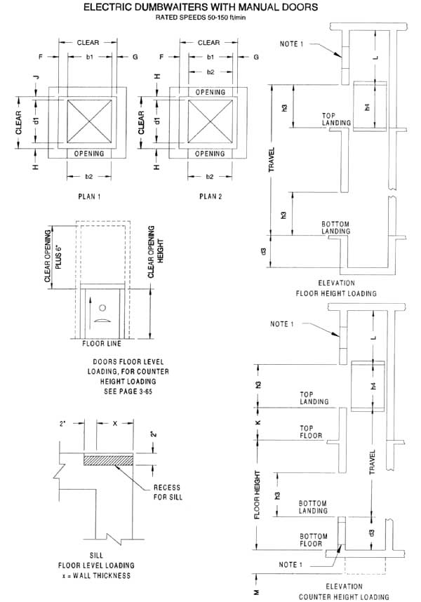
- Floor level loading or counter height loading capability to suit particular vertical material handling requirements.
- Counterweighted traction design utilizes high?rise elevator technology.
- State of the art microprocessor controls allow custom programmed operation to fulfill individual project requirements.
- Higher speeds minimize waiting time and maximize staff efficiency.
- INTERCOM (OPTIONAL): Press to talk intercom system shall be furnished in each pushbutton station. Each station shall have a combination speaker-microphone, and a button for communication with each floor selectively, or at all floors at once.
- DRAWBRIDGE (OPTIONAL): Floor loading models with bi-parting door and car gates shall be equipped with drawbridge to provide smooth entrance for wheeled carts. Drawbridge shall be raised and lowered by opening and closing of car gate.
- SELF-SUPPORTING TOWER (OPTIONAL): Components shall be carried on a self-contained, rigidly braced, structural steel angle tower extending full height of the hoistway.
- POWER-OPERATED HOISTWAY DOORS AND CAR GATE(S) (OPTIONAL): Car gate(s) shall be motorized, and shall be equipped with magnetic clutch assembly which shall power operate the hoistway doors.

Section 14250 Dumbwaiters
Part 1 – General
1.01 Section Includes
A. Furnish and provide all materials and labor necessary for the complete installation of one Ambassador TR dumbwaiter.
B. Obtain information on conditions affecting work at jobsite. Include verification of dimensions, field material for anchoring, accessibility and storage space. Verify voltages and outlets on electrical drawings.
1.02 Work Done By Others
A. Suitable, legal, two-hour fire-rated hoistway, if consistent with building construction.
B. Hoistway door walls must not be erected until doors are set in place.
C. Electrician shall furnish power supply with a line disconnect switch immediately adjoining the controller cabinet.
D. Hoistway free of all pipes and obstructions.
E. All bracket fastening inserts and other steel required for support of guide rails and brackets.
F. Painting of exterior walls and prime finished components which are exposed to view, including inside of car, car gates and doors.
G. Machine area lighting and convenience outlet.
1.03 References
Design and installation shall be in compliance with regulations and all governing agencies. Lift shall be subject to local, city and state approval prior to installation, along with city and state inspection after installation. Special local requirements shall be determined and handled locally by distributor with manufacturer’s agreement.
1.04 Submittals
Submit drawings or manufacturer’s literature for approval. Drawings shall show rough?in requirements and wiring requirements.
1.05 Substitutions
No substitutions will be considered unless written request for approval has been submitted by the bidder and was received by the architect at least ten (10) days prior to the date of receipt of bids. Each such request shall include the name of the materials for which it is to be substituted and a complete description of the proposed substitute including drawings, cuts, performance and test data, a list of projects of similar scope, photographs of existing installations and any other information necessary for evaluation.
1.06 Testing
The dumbwaiter shall be tested after installation to demonstrate:
- Accuracy of stops.
- Operation of hoistway door locks and car gate switch(es)
- Operation of final terminal switches.
- Operation of pushbutton and key switches.
- Capacity load test. Operate dumbwaiter for a period of twenty (20) minutes with a capacity load. Run dumbwaiter from top terminal floor to bottom floor with one minute between starts after each stop.
PART 2 – PRODUCTS
2.01 Manufacturer
Matot Inc., Bellwood, Illinois
2.02 Product Type
A. Model shall be the Ambassador TR traction dumbwaiter.
B. Car shall have clear inside dimensions of inches wide x ___ inches deep x ___ inches high, and have one removable shelf. Capacity to be ___ pounds. Dumbwaiter to serve __ stops, and ___ openings, located on: [ ] same, [ ] opposite, [ ] adjacent side(s) of the hoistway. The car shall stop [ ] at counter height or [ ] floor level. The travel distance shall be _ feet. Power supply shall be ___ volt, ___ phase, ___ hertz.
C. All equipment shall be manufactured in accordance with the latest edition of the ANSI 17.1 code for elevators, escalators and dumbwaiters.
2.03 Fabrication
A. CAR: The car shall be constructed of: 16 gauge [ ] stainless steel with no.4 satin polish finish or [ ] carbon steel with prime finish. Car shall have one removable shelf. An electrical light fixture shall be recessed in the ceiling. Floor loading models shall have a reinforced floor.
B. CAR GATE: The car shall be equipped on each open side with a gate matching the car construction and finish. The gate shall be vertical [ ] bi-parting or [ ] slide up design. Car gate(s) shall be manually operated unless power operation is specified.
C. GUIDE RAILS: Steel channel rails 2 7/8″ wide x 1 3/4″ deep and 1/4″ flange shall be furnished to guide the car. Guide rails shall be mounted to the floor slabs and hoistway wall with steel brackets.
D. MACHINE: Machine shall be the traction type. Motor shall be of ample horsepower to lift the rated load at the rated speed, with a high starting torque and low starting current. It shall be equipped with a spring applied and electrically released brake. Machine shall be located at the top of the hoistway and mounted on a structural steel base. The traction sheave shall be semi-steel, with machine grooves designed to provide adequate traction, and long cable life.
E. CONTROLLER: Controller shall be wall mounted type with lockable door, located on hoistway outer wall in sight of machine access door. Controller shall be programmable solid state and Underwriters Laboratories, Inc. listed.
F. OPERATIONAL CONTROL: Operation shall be automatic call and send. A pushbutton station with one button for each level served, shall be furnished at each door. It shall be possible at each level to call the car or send it to any other level. Pushbuttons shall be inoperative while car is in transit, and for a few seconds after arrival at the selected level. Pushbuttons shall have stainless steel face plates.
G. SIGNAL DEVICES:
- “Door Open” call buzzer?shall sound when a pushbutton is pressed and a hoistway door or car gate is open.
- “Car Here” light and chime ? shall be located in each pushbutton station. Chime shall indicate car arrival. Light shall indicate car presence.
- Combination “Door Open” and “In Use” light ?shall be located in each pushbutton station. Light will illuminate when car is in transit and when a pushbutton is pressed and a hoistway door or car gate is open.
H. LEVELING ACCURACY: If car stops above floor level, car floor shall be no more than 1/2″ above or below the level of hoistway door sill. If car stops at floor level, car floor shall be no more than 1/4″ above or below the level of the hoistway door sill.
I. HOIST ROPES: Minimum of two 1/4″ x 3 x 19 traction steel cable with safety factor per code.
J. FINAL TERMINAL STOPPING DEVICES: Provide per code.
K. GUIDE SHOES: Guide shoes shall be adjustable, renewable dry type.
L. HOISTWAY DOORS: Doors shall be vertical sliding [ ] bi-parting or [ ] slide up design. Each door shall bear the Underwriters “B” label and shall be rated for application in; (a) masonry shaft and (b) metal stud drywall shaft. Hollow metal door panels shall be; 16 gauge [ ] stainless steel with no.4 satin polish finish or [ ] carbon steel with prime finish. Welded unit wall frame, including jams, trim and sill shall be; 16 gauge [ ] stainless steel with no.4 satin polish finish or [ ] carbon steel with prime finish. Doors shall be manually operated unless power operation is specified. A door lock and contact shall be provided on each door.
M.MACHINE ACCESS DOOR: Hinged access door shall be 24″ wide x 24″ high and shall be furnished at machine location for service and maintenance. Access door shall be; 16 gauge [ ] stainless steel with no.4 satin polish finish or [ ] carbon steel with prime finish.
N. COUNTERWEIGHT: The counterweight shall be equal in weight to that of the car plus 40% of the rated capacity.
O. INTERCOM (OPTIONAL): Press to talk intercom system shall be furnished in each pushbutton station. Each station shall have a combination speaker-microphone, and a button for communication with each floor selectively, or at all floors at once.
P. DRAWBRIDGE (OPTIONAL): Floor loading models with bi?parting door and car gates shall be equipped with drawbridge to pro vide smooth entrance for wheeled carts. Drawbridge shall be raised and lowered by opening and closing of car gate.
Q. SELF-SUPPORTING TOWER (OPTIONAL): Components shall be carried on a self-contained, rigidly braced, structural steel angle tower extending full height of the hoistway.
R. POWER-OPERATED HOISTWAY DOORS AND CAR GATES) (OPTIONAL): Car gate(s) shall be motorized, and shall be equipped with magnetic clutch assembly which shall power operate the hoistway doors.
2.04 Performance
A. Rated load __ pound capacity.
B. Rated speed shall be F.P.M.
- If rated speed is 50 F.P.M., drive and control shall be single speed A.C.
- If rated speed exceeds 50 F.P.M., drive and control shall be variable voltage, variable frequency A.C.
C. Leveling Accuracy: Car floor shall be no more than 1/2″ above or below the level of the hoistway door sill.
Part 3 – Execution
3.01 Installation
A. Coordinate work with general contractor.
B. Leave standard electrical connection drawings with electrical contractor to make final electrical connection. Wiring within unit shall be done as part of work of this section, 20 amp circuit required.
C. The installation of the dumbwaiter shall be made in accordance with the approved plans and specifications and manufacturer’s installation instructions.